Pressure Penetration in Abaqus
Table of contents
Seals are common structural components that often require design analysis. Abaqus can perform non-linear Finite Element Analysis (FEA) of seals and verify seal performance with the “Pressure Penetration in Abaqus” function.
In these analyses, seal deformations and stresses, as well as contact pressure distribution, can be determined. Seal studies can be made more accurate and realistic by considering the pressure penetration effects between the contact surfaces and the seal using Abaqus.
This feature simulates fluid penetration or pressure penetration between touching surfaces using the pressure penetration option. Air pressure penetrates the joint and stresses the surfaces forming the joint until a region of the surfaces is reached where the contact pressure between the abutting surfaces exceeds the critical value specified in the pressure penetration option, thereby preventing further penetration.
In this quick guide, we’ll perform a non-linear Finite Element Analysis of a seal to verify its performance using the ‘Pressure Penetration’ function in Abaqus.
Finite Element Model of a Rubber Seal and Steel Pipe
Geometry
Here, we’ve created a 3D model of the assembly: it consists of 2 parts: a rubber seal in green and a steel tube in white. Both components are modeled using the symmetrical support condition and are loaded at one or more ends by the fluid or air pressure.
Pressure penetrates the rubber seal until an area of the surfaces is reached where the contact pressure between the abutting surfaces exceeds the critical value. This will prevent further penetration.
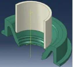 Figure 1: Geometry of the rubber seal and steel pipe in Abaqus/CAE
Material Properties
The rubber seal is modeled with a simple Neo Hooke material model (Hyperplastic) with the parameters C10 = 0.752 and D1 = 0.026.
The steel pipe is modeled as a rigid body by applying a rigid body constraint.
Meshing
The rubber seal and the steel rod are meshed with hex elements. The assigned element type is C3D8R in Abaqus/Standard calculations.
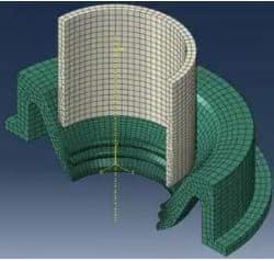 Figure 2: meshing of rubber seal and steel rod in Abaqus/CAE
Contact properties
The contact properties are as follows:
- tangential behavior: 0.1 as coefficient of friction
- normal behavior: hard contact
Deformation Analysis of a Rubber Seal for a Steel Pipe
Step 1
The cut surface of the rubber seal is symmetrically fixed in the Z direction throughout the simulation. In addition, the outer surface of the seal is supported.
The steel rod is moved down 10mm to insert into the rubber seal in.
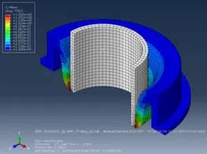 Figure 3: Deformed shape after step 1
Step 2
Now we simulate the effects of pressurized fluid entering the modeled area from above and applying pressure to the exposed portion of the rubber seal.
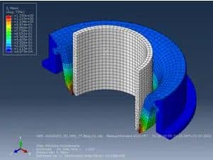 Figure 4: Deformed shape after step 2
Step 3
The steel pipe is moved in the horizontal direction by 3mm. This allows the fluid pressure to be partially blocked and partially enabled due to the change in the contact conditions.
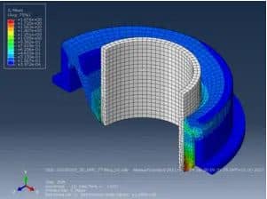 Figure 5: Deformed shape after step 3
Defining the Pressure-Penetration Interaction
The contact pair approach is used to model the contact where pressure penetration is likely to occur.
 Figure 6: Contact pair
The previously defined contact interaction can now be selected so that the main and secondary interfaces are already known. An area must be defined on both the main and secondary surfaces in which the pressure is initially applied. The area on the secondary surface is mandatory.
In this case, the areas indicated by arrows in Fig. 7 are selected. The pressure then automatically penetrates to the first sealing tooth.
A fluid pressure must also be specified. This is the pressure applied in the non-contact area. In this case, a fluid pressure of 0.05 MPa is chosen, which is ramped up during the simulation step.
‘Critical Contact Pressure’ determines the critical value of the contact pressure between the abutting surfaces, preventing further penetration.
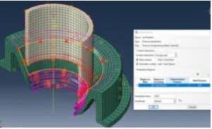 Figure 7: Pressure-penetration interaction
Finally, a self-contact is assigned to the rubber seal.
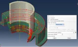 Figure 8: Self-contact interaction
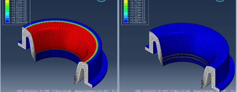
The PRESS field output is requested. This is the pressure exerted on the surface due to pressure penetration. This shows where the pressure is being applied as well as its current size.
Results
As Figure 9 shows, the fluid pressure can be stopped through contact.
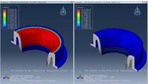 Figure 9: PRESS after step 2
After the pipe is moved laterally, the contact of the first sealing tooth on the left side is separated. This enables pressure penetration into the second tooth.
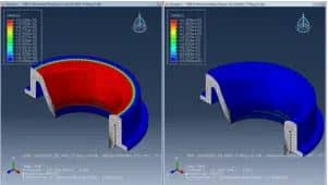 Figure 10: PRESS after step 3
Check out our Simulation Tutorials in the Knowledge Hub for more expert guidance on Abaqus best practices.

