Mechanical Interfaces – Making Positioning Parts Snappier
When designing parts that are going to be assembled together, there’s a common workflow that is generally advocated in the training manuals for CATIA V5 and 3DEXPERIENCE:
- Create geometry for each part in the assembly
- Insert parts into a product in order to assemble them
- Use Constraints or Engineering Connections to position all parts correctly using whatever geometry gives you the right result.
All very well, and in the ideal world where there are no part changes and only small numbers of parts in an assembly, this works. However, in the real world, there is often the following steps added on…
- Open Assembly at a later date
- Find out that the geometry of one of the parts has been updated
- Notice in dismay that all of the constraints have broken as a result
- Try to repair the constraints for all 78 nuts, bolts and washers that are no longer positioned correctly.
- Give up, delete the constraints, position parts manually and Fix in space.
- Hope that any misalignment from future updates gets noticed before the assembly is released.
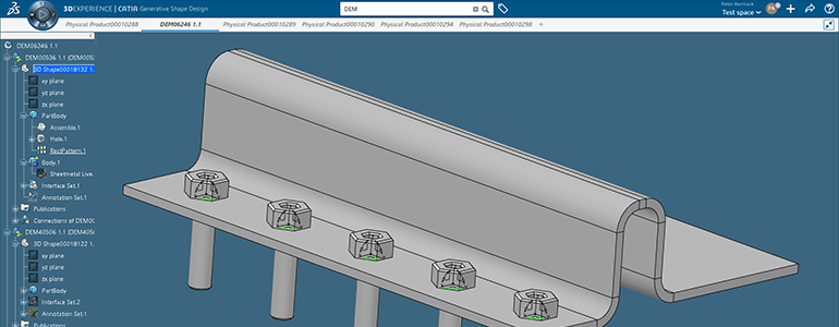
We’ve all been there, and even as an advocate of doing things “properly” in CATIA, I do understand the frustrations. But there is a better way that was introduced at 2018x. The idea is that when designing most parts, you will probably know how that part is going to interface with the parts it has assembled with, you’ve placed a hole for the bolts, a groove for the O-rings, a face to push up against etc…
…So why not declare at that point what sort of interface should go there?

With the mechanical interference tool in Part Design, you can declare your interfaces up front in the part, so assembling them later on is as easy as this:
You might not yet see the point of doing things this way around; but consider what happens if a part is changed. With normal constraints, the person modifying a part has no idea if they’re breaking constraints and positioning in assemblies they might not have opened, causing problems further down. With interfaces, the person modifying the part knows straight away they need to fix it, and they need only fix it once rather than fixing it for every instance of that part in every assembly.
You can start to see why doing positioning this way starts to be a huge timesaver; especially for standard parts you use in large numbers.
If you need further demonstrations of the functionality or need some help with training or just generally feel like you’d like us to consult on your CAD processes to see if there are any improvements to be made in how design work happens, do get in contact.
Discover more about 3DEXPERIENCE

